Heavy Duty Escalator ,Step Chain Roller Outside Link, Opaque Balustrade, type 1000
Product Introduction
Our HD20 type of heavy-duty escalator is developed by our international vision and experienced professional technical design team.
The product highlights its personalized design, professional technology, unique features, safety and reliability, outstanding operational performance, high efficiency and energy savings, and stylish appearance.
The concept of safety, green and environmental protection enables the HD20 escalator product to operate in safe, low-cost, low-noise, low-power, oil-free, quiet and natural conditions, giving riders a truly attractive ride experience.
Application scope
HD20 type heavy duty escalator can be widely used in a variety of public transportation and high-rise occasions and the environment in indoor or outdoor:
- Metro / Subway
- Train station
- Transition hub
- Airport
- Exhibition center
Basic Technical Specifications
| Escalator Code |
EN115-1:2017 |
| Max. Rise (m) |
26 |
| Incline (degree) |
30 / 27.3 |
| Speed (m/s) |
0.65 / 0.5 |
| Balustrade |
Stainless steel opaque/ Glass |
| Step Width |
1000 |
| Number of Flat Steps |
4/3/2 |
| Energy Saving Mode |
VF drive / None |
| Environment |
Outdoor / Indoor |
| Step |
Aluminum |
| Floor Plate |
Aluminum / Stainless steel |
| Handrail drive |
Newel drive / Traction wheel |
| Handrail type |
V type / C type |
| Safety factor |
>=5 |
Design life calculation basis
| Typical metro traffic flow patten |
Hours |
percentage |
Passenger load / step (kg) |
Brake load percentage |
| 20 years, 52 weeks, 20 hours/day |
6.67 |
33.33 |
120 |
120% |
| 13.33 |
66.67 |
72 |
60% |
| Total |
20 |
100 |
Equivalent braking load |
78.16% |
*According to the specific load and life requirements of different customers, different drive machine, step chains and other major components can be selected to meet the special load requirements of customers.
Key Component Mature Personalized Design Highlight
Product basic structure description
Truss
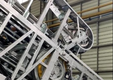
The escalator truss is using tubular profile welding steel structure design. Its upper chord and lower chord use angular steel L120x60x5/6/7.1/8. The truss can support rise up to 20 meters. The length 15830mm is the maximum DBE (distance between two end support) of escalator, and with one intermediate support, the cross distance between end support can reach length 30600mm. The deflection of truss is less than 1/1500 which is verified by calculation and confirmed through full load test according to the code EN115 requirement. The truss is powder coated for corrosion protection for indoor unit and apply hot dip galvanized for outdoor application. The truss can be designed split into 2 or 3 or 4 pieces for container shipment.
Driving Machine
The driving machine is designed to use worm gearbox reducer as standard configuration and helical gearbox reducer optional. The motor is a high efficiency design which energy efficiency level IE2 as standard and supper high level IE3 optional. There are two driving machine arrangement, single drive machine and dual dive to support the need of the different rise.
Step chain and step
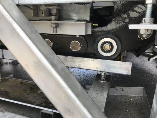
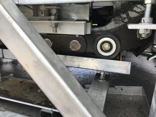
The step chain is designed for its pitch is 133.33mm, which is a popular size in the industry to support the step distance of 400mm (133.33x3). Hence, the spare part for them is available and popular in the spare part market. Two kinds of steps will be provided, standard for entire die cast Aluminum step, assembly type stainless steel step is an option. The steps are powder coated with black or gray color. With three sides yellow demarcation optional.
Track system
The track system consists of upper curve, lower curve and incline section. The upper curve and lower curve are welding track block design.
The incline section track is track profile’s structure which profile edge as guidance function for step chain roller and step roller running. This personality structure design is beneficial to the reliability and stability of the running guide of the steps and reduces the lateral movement.
Balustrade
The balustrade is the stainless steel opaque or safety glass panel. The LED under handrail lighting, brush guard lighting and comb lighting are optional features for escalator appearance beauty. The skirt panel, inner and outer decking use 2 mm hairline stainless steel sus304. The exterior panel will be customized design and material use 1.5 mm thickness stainless steel sus304.
Comb support plate
The comb support plate area is an extreme safety risk range and needs to be focused on. We have reinforced the comb support plate strength so that under the condition applying the load 6000N/mm2, its deformation is not more than 2mm. The upthrust track intend into the comb plate design is one of our safety measures to guaranty steps not lift up hitting comb.
Lubrication device
Lubrication device is an efficient gear pump device for better lubrication. It is a green design to reduce oil waste and avoid environmental pollution.
Control system
The control system consists of a controller and safety devices which are compliant with EN115-1:2017 code requirement. The controller applies microprocessor control board and equips all kinds of safety switches and different sensors to monitor escalator running. The controller supports VF drive to switch into idle model to lower escalator speed for energy saving.
| Escalator Safety Device |
| Standard Safety Device - EN115:2017 requirement compliant |
| 1 |
Lack of phase or error phase protection |
In case detected lack of phase or error phase, the escalator will automatically stop the operation. |
| 2 |
Motor overload protection |
When the current is over 15% the escalator will stop automatically. |
| 3 |
Electrical appliance loop protection |
It offers the automatic circuit disconnection device to protect the circuit and power supply components of escalator. |
| 4 |
Handrail entry protection |
Protection will activate to stop escalator running upon detection of objects jammed into handrail entry. |
| 5 |
Comb plate safety device |
When some foreign substance has been clipped in or between the combs, the escalator will automatically stop the operation |
| 6 |
Step sagging protection device |
When the step is detected broken or serious deformation, the escalator will stop running automatically before then step entering into the comb plate. |
| 7 |
Main Drive Broken Chain Monitoring Device |
When the main drive chain has over stretched or broken, the monitoring device will be activated to stop the escalator operation. |
| 8 |
Step Chain Safety Protection |
When the step chain has over stretched or broken, the protection device will be activated to stop the escalator operation. |
| 9 |
Over speed protection |
Apply sensor to monitor the main drive sprocket speed directly, protection will activate upon detection of operating at the speed 20% higher than rated speed, the main power supply will be cut for escalator stop operating. If the escalator is over 6 m rise, the equipped with an auxiliary brake, then this emergency brake device will be activated to break the escalator running. |
| 10 |
Un-Intentional Reversal Protection (NRD) |
Apply sensor to monitor the main drive sprocket rotation direction, protection will activate upon detection of unintentional reversed movement (from the set direction) of the steps and handrails, the escalator be stop operating. If the escalator is over 6 m rise, an auxiliary brake is equipped, then this emergency brake device will be activated to break the escalator running. |
| 11 |
Demarcation line |
The yellow demarcation line is located in the front position and two sides of the step tread to warming passengers step away the risky area to avoid being entrapped into the gap between the edge of the adjacent step and at the gap between the skirt panel. |
| 12 |
Emergency stop button |
Push the emergency stop button to stop the escalator in case an accident happens. |
| 13 |
Skirt Panel protection |
When some foreign substance has been clipped in between the skirt panel and the step, the escalator automatically stops the operation. |
| 14 |
Brake protection |
When the electric force falls short of supply or it acts any of the safety device, the working brake function goes into effect by the safety device through the spring resilience action for breaking the escalator to stop the operation. |
| 15 |
Safety inspection switch |
It is a safety device to prevent the escalator from starting during the inspection and maintenance. |
| 16 |
Under step lighting |
Illumination exists in the upper and lower ends of the escalator, the lower part of the step in order to remind the passengers of the security matters. |
| 17 |
Alam bell starting device |
The alarm bell rings when it starts the escalator in order to remind the passengers of the security matters. |
| 18 |
Handrail broken device |
When the handrail is breakage, the escalator automatically stops the operation. |
| 19 |
Handrail speed monitoring device |
Protection will activate to stop escalator upon detection of a handrail speed deviation of more than +- 15% to the step speed within a time frame of 5 to 15s. |
| 20 |
Skirt Panel Bush Guard |
The brush guard has been installed between the skirt panel and the steps will prevent the passengers from touching the skirt panel. |
| 21 |
Missing step device |
A missing step can be detected and the escalator stopped before the trap window emerges from the comb. |
| 22 |
Brake release detection |
Brake adding detection switch prevents the motor running without brake release to avoid burning the machine motor. |
| 23 |
Floor plate Contact Device |
Protection against the risk of passengers and maintenance people falling down into the machine room where the floor plate is removed. Service people have to use an inspection box to run the escalator by the inspection model under the condition of floor plate being removed. |
| 24 |
Auxiliary Brake |
Standard configuration |
| 25 |
Fire-proof rolling door device |
When this device comes action, it can stop the escalator operation. This device has to be installed near the escalator in the building. |
Escalator Safety Device Arrangement
Pre-assembly service
We provide escalator preassembly service. Customers can order a semi-product which is an entire escalator except controller were offered by local supply in order to meet the needs of the local special.


 Your message must be between 20-3,000 characters!
 Please check your E-mail!
  Your message must be between 20-3,000 characters!
 Please check your E-mail!


